PBX
Introduction
The PBX make and model is selected during the installation of Avaya Messaging. The installer will automatically append the specific PBX related settings to the appropriate fields when you choose a template. Due to the variance in both hardware & software configurations that are involved in a PBX, you may have to fine-tune the settings to match your site’s specific requirements. From the PBX settings, you will have the ability to specify exactly how the voice server will interact with the PBX and customize the different types of codes which may be involved in the communication between devices.
This chapter explains all the fields that are involved in a PBX configuration so please use it as a guideline when creating a custom setting for your site.
|
Note: Due to the sensitive nature of server configuration, it is recommended that you backup your settings and other important files (e.g. messages, custom prompts) before attempting significant changes.
|
PBX Buttons
|
Button
|
Description
|
|

|
Save all the settings that you have modified in the current PBX properties.
|
|

|
Refresh the properties of the current PBX to view the latest changes in effect.
|
|

|
Modify the Manufacturer / Model of the current PBX.
|
|

|
Add New PBX.
|
|

|
Launch the SIP Configuration Wizard (only functional under SIP integration).
|
|

|
Start the Dial Plan editor (see International Dial Plan on page 673 for details).
|
General
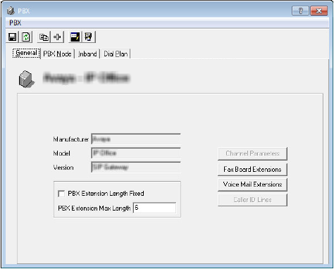
The General tab of PBX allows you to view your current PBX information. You may also modify your extension assignments manually from this section.
General Tab
Manufacturer: This field displays the manufacturer of your PBX.
Model: This field displays the model of your PBX.
Version: This field displays the version of your PBX.
PBX Extension Length Fixed: Enable this checkbox to force the digit length of the extension (e.g. length of 3 will translate to extensions in the form of 001 instead of being simply 1). The default fixed length will be 3 but may be modified using this field.
PBX Extension Max Length: Enter the maximum desired digit length of the extension here. If the PBX Extension Length Fixed checkbox is enabled, the extension length will be forced to match the number of digits defined here. If the checkbox is not enabled, the extension length can vary between 1 digit to the assigned maximum in this field.
Channel Parameters: This button allows you to modify the default parameters for a Dialogic Voice Board.
Fax Board Extensions: This button allows you to manually map a port number to the extension number for Fax purpose.
Voice Mail Extensions: This button allows you to manually map a port number to the extension number for Voice Mail purpose.
Caller ID Lines: This button allows you to manually integrate outside Caller ID equipment if your PBX does not support it by default.
PBX Node
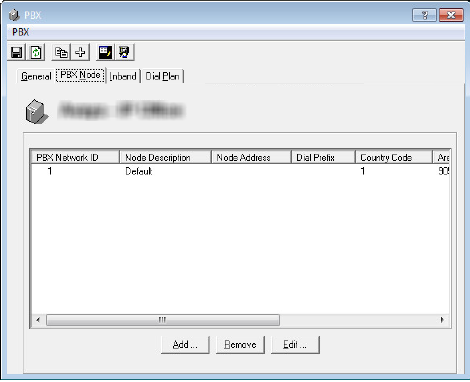
The PBX Node tab of PBX allows you to specify additional PBX Nodes manually so that the server can utilize multiple PBXs at the same time. Multiple server nodes must be numbered sequentially starting with 1 (e.g. 1 2 3 4...).
PBX Node Tab
Display Field: This field displays all the PBX nodes that have been defined.
Add: Click this button to add a new PBX node. Refer to Add / Edit PBX Node on page 30 for more information.
Remove: Click this button to remove one of the current PBX nodes.
Edit: Click this button to edit one of the current PBX nodes.
Inband
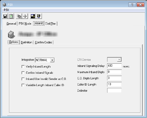
The Inband tab of PBX allows you to simulate a C.O. Line identification feature if your system does not have it natively.
Inband Tab
Options
Integration: From the dropdown menu, select the type of integration your system uses.
Verify Inband Length: Enable this checkbox to verify if all inband codes are the same length. This ensures that the inband codes being sent from the PBX are correct. This setting is applicable to Mercator and Matra switches.
Confirm Inband Signals: Enable this checkbox to indicate that the system must confirm the inband signals. This is applicable to Mercator and Matra switches. You must also configure the corresponding tab when you enable this option.
Inband Use Invalid Sender as C.O.: Enable this checkbox to indicate that the system is to use an invalid sender as a C.O. This is applicable to Mercator and Matra switches.
Variable Length Inband Caller ID: Enable this checkbox to indicate to the system that it can receive calls from integers of variable length. This option is used for Inband integration for the Mercator PBX.
CTI Device: From the dropdown menu, select the device (or the port) that will be used.
Serial Integration Device: This dropdown menu is only available when you choose MD110, MCI, CTI, or ASCOM from Integration dropdown list. From the dropdown list, select the Serial Integration device (or the serial port) that is going to be used.
Inband Signaling Delay: Enter the delay (in milliseconds) between packets.
Maximum Inband Digits: Enter the maximum inband digits that the system can accept.
C.O. Digits Length: Enter the digit length of the C.O. that will be accepted by the system.
Caller ID Length: Enter the digit length of the phone number that the Caller ID receives.
Delimiter: Enter the delimiter value. Leave this value as default. This field is usually used for troubleshooting purposes by the technicians.
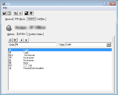
Definition
The definition tab is only available on Inband integrations.
Add: Click this button to add a new entry.
Delete: Click this button to delete the currently selected entry.
Move Down: Click this button to move the selection bar down.
Move Up: Click this button to move the selection bar down.
Code: Enter the code that is going to be used.
Type: Define the function that the selected code is going to be associated with. The following are the choice of functions available.
•Not Defined
•Login
•No Answer
•Busy
•C.O. Call
•Record Conversation
•Invalid
•Refresh Message Light
•Extension Verify
•PBX Authentication
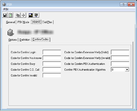
Confirm Codes
This tab is only necessary for PBXs that require the inband codes to be confirmed.
Code for Confirm Login: Enter the confirmation code for login event.
Code for Confirm No Answer: Enter the confirmation code for no answer event.
Code for Confirm Busy: Enter the confirmation code for busy event.
Code for Confirm C.O. Call: Enter the confirmation code for C.O. call event.
Code for Confirm Invalid: Enter the confirmation code for invalid event.
Code for Confirm Extension Verify (Valid): Enter the confirmation code for valid extension verification event.
Code for Confirm Extension Verify (Invalid): Enter the confirmation code for invalid extension verification event.
Code for Confirm PBX Authentication: Enter the confirmation code for PBX authentication.
Confirm PBX Authentication Algorithm: From the dropdown menu, select the algorithm which will be used during PBX authentication.
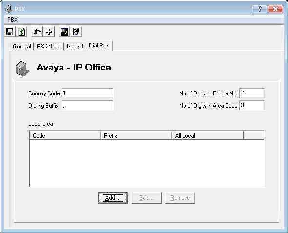
Dial Plan
The Dial Plan tab is used to define how the system parses outgoing telephone numbers.
For example, if you dial 19057079700, the system will break this up into Country Code (1), Area Code (905), and the telephone number (7079700).
Different world regions have different rules. Use Dial Plan to configure the rules for your location.
These rules are applied to all outgoing calls.
Country Code: Specify the Country Code for your area. For example, in North America, the Country Code is 1.
Dialing Suffix: When dialing a call, the system will append this character to the end of the number entered to tell the PBX to place the call. This varies with your system.
No of Digits in Phone No: Enter the number of digits in a telephone number for your region.
No of Digits in Area Code: Enter the number of digits in an area code for your region.
Some areas may be serviced using numbers with different configurations, such as multiple area codes for a single city. The system will process the plans from the top down until it finds a match to the dialed number.
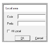
Click Add to create a new Local area Dial Plan. Or select a plan, then click Edit to modify the settings.
Code: Enter the area code / city code for one region in this space. Create a new rule for each region.
Prefix: If the local number requires an additional code at the start, put that value here. Note that this option is unavailable if All Local is enabled.
When a number is entered, the system will search through these rules to find a match. The number will then the correctly parsed (prefix, area code / city code, number), the standard rules are applied (country code, number of digits in the number and area code, etc.), and it is passed on to the PBX for processing.
Other PBX Related Options/Configurations
The following lists common scenarios and solutions involved with PBX settings.
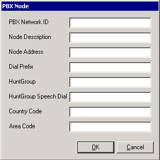
Add / Edit PBX Node
If you have multiple PBXs in your system, you will have to define a PBX node so that the server will know where the calls are routed to.
PBX Network ID: Enter the PBX node network ID. Node IDs must be sequential starting with 1 (e.g. 1 2 3 4 ...).
Node Description: Enter an unique name/description for the PBX node.
Node Address: Enter the PBX Node IP address.
Dial Prefix: Enter a dial prefix for the PBX node.
HuntGroup: Enter the HuntGroup of the PBX node.
HuntGroup Speech Dial: Enter the HuntGroup of the PBX node which is used for speech dialing as opposed to typical integration.
Country Code: Enter the Country Code from which most calls will be made.
Area Code: Enter the Area Code from which most calls will be made.
Add / Edit PBX Template
PBX templates will make the configuration of a site easier for you by applying the typical settings for a selected PBX make and model. However, since each site is unique, you must fine tune the settings to ensure proper functionality.
Adding a New PBX Template
If the PBX you wish to use does not exist as a default template, you may add your own template for easier reference.
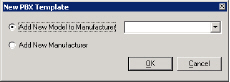
When you click on the Add PBX button from the PBX properties, the above window will appear.
Add New Model to Manufacturer: Select this radio button to add another PBX Model to the list of manufacturers that are already available.
Add New Manufacturer: Select this radio button to create a new PBX manufacturer and model.
Editing a PBX Template
If you decide to change the PBX in your system you can reflect the changes to the UC Admin by modifying the current PBX from the PBX Properties.
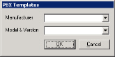
When you click on the Modify PBX Template button from the PBX properties, the above window will appear.
Manufacturer: From the dropdown menu, select the manufacturer of the PBX.
Model/Version: From the dropdown menu, select the specific PBX model/version.
The selections made here will be reflected on the General tab of the PBX properties.
Caller ID Lines
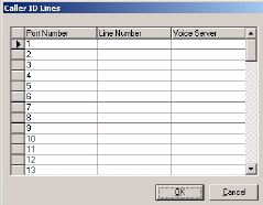
While the UC system supports Caller ID, some PBX systems require that all calls first go through a third-party Caller ID device (Rochelle, for example), which then passes the call to the PBX.
Port Number: Enter the number of the first port.
Line Number: When you click on this field after entering the Port Number, the system prompts you to confirm the auto adding of all line numbers.
Voice Server: Enter the PBX node.
Channel Parameters (for Dialogic)
When you install the UC system, the system automatically pre-loads the required settings regardless of the voice board it has detected.
Channel Parameters allow you to change one or more of these predetermined settings. You can also configure UC Voice Mail to integrate with other PBX systems here.
When you install the UC system with a Dialogic voice board, the Dialogic dialog box allows you to change one or more of these pre-installed parameters.
|
Note: Select Internal, External or Other to indicate the source of the call and the strength of the signal.
|
|
Field
|
Function
|
|
Start Delay
|
The delay, once dialing has been completed and prior to analysis for Cadence Detection, Frequency Detection, and Positive Voice Detection, in 10 msec increments.
The default is 250.
|
|
Continuous No Signal
|
The maximum time of silence (no signal) allowed immediately after Cadence Detection begins. If exceeded, a no ringback is returned in 10 msec increments.
The default is 40000.
|
|
Loop Current Delay
|
The delay after dialing has been completed and before beginning Loop Current Detection, in 10 msec increments. A value of –1 will Disable Loop Current Detection.
The default is 4000.
|
|
Loop Current Delay 1
|
The delay after Loop Current Delay detects a transient drop in loop current and before Call Analysis returns a connect to the application, in 10 msec increments.
The default is 100.
|
|
Hello Edge
|
The point at which a connect will be returned to the application.
Valid Range 1 (rising edge – immediately when a connect is detected) or 2 (falling edge – after the end of the salutation.
The default is 2.
|
|
Continuous NonSilence
|
The maximum length of the first or second period of non-silence allowed. If exceeded, a no ringback is returned in 10 msec increments.
The default is 6500.
|
|
Reserved
|
Reserved. This must be set to 0 (zero).
|
|
Intercept Mode Flag
|
This parameter enables or disables SIT-Frequency Detection, Positive Voice Detection (PVD), and/or Positive Answering Machine Detection (PAMD), and selects the mode of operation for Frequency Detection.
The default is 4. Do NOT alter this value. This value is only used for troubleshooting.
|
|
Reserved
|
Reserved. This must be set to 1.
|
|
Maximum Answer
|
The maximum allowable length of Answer Size. When Answer Size exceeds Maximum Answer, a connect is returned to the application in 10 msec increments.
The default is 10000.
|
|
Answer Deglitcher
|
The maximum silence period allowed between words in a salutation. This parameter should be enabled only when you are interested in measuring the length of the salutation. Measured in 10 msec increments. A value of –1 disables this option.
The default is –1.
|
|
Dial Tone Present
|
The length of time that a dial tone must be continuously present. Measured in 10 msec units.
The default is 1000.
|
|
Dial Tone Not Present
|
The maximum length of time to wait before declaring dial tone failure. Measured in 10 msec increments.
The default is 3000.
|
|
Dial Tone Debounce
|
The maximum gap allowed in an otherwise continuous dial tone before it is considered invalid. Measured in 10 msec increments.
The default is 100.
|
|
PAMD Fail Time
|
Maximum time to wait for Positive Answering Machine Detection or Positive Voice Detection after a cadence break. Measured in 10 msec increments.
The default is 4000.
|
|
Minimum PAMD Ring
|
Minimum allowable ring duration for Positive Answering Machine Detection, in 10 msec increments.
The default is 1900.
|
|
No Answer
|
Length of time to wait after first ringback before deciding that the call is not answered. Measured in 10 msec increments.
The default is 30000.
|
|
Maximum Inter-ring Delay
|
Maximum time to wait between consecutive ringback signals before deciding that the call has been connected. Measured in 10 msec increments.
The default is 8000.
|
Edit Disconnect Tone
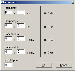
The UC system allows you to manually define the frequency of the signal used for the PBX disconnect tone.
|
Note: If no disconnect tone has been detected, you must first determine the frequency of the unrecognized prompt. To do this, use a secondary audio application (Prompt Studio, for example). In most cases, however, you do not need to make any changes since your disconnect settings have been pre-set during installation.
|
Frequency 1: Enter the first frequency.
Frequency 2: Enter the second frequency.
Cadence On: Enter the amount of time that the signal is on.
Cadence Off: Enter the amount of time that the signal is off.
No of Cycles: Enter the number of cycles that the system analyses before reporting the disconnect signal.
|
Note: Two cycles are recommended for the latter field.
|
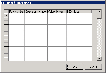
Fax Board Extension
Specifying a fax board extension allows you to match a port number to an extension number. When a fax is received by the voice mail system, the fax call will be transferred to the specified extension.
|
Note: Fax board settings must be configured only if you have either fax mail or fax on demand software installed. In addition, a fax board must be installed on the fax server.
|
Port Number: Enter the fax port on the installed fax card.
|
Note: You must enter the port numbers in consecutive order. If you are specifying more than one fax port, they must be specified in numerical order.
|
Extension Number: Enter the analog extension connected to the associated port.
Voice Server: This field should be automatically defined during installation. If not, enter the Voice Server name.
PBX Node: This field should be automatically defined during installation. If not, enter the PBX node.
|
Note: PBX Node is only required if you have 2 or more nodes. These must be numbered sequentially starting with 1 (e.g. 1 2 3 4...).
|
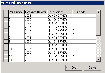
Voice Mail Extension
In the UC system, you must match the port number with the line number declared in the PBX configuration.
|
Note: These are predefined during installation of the switch. For more information, refer to the appropriate TAPI guide.
|
|
Note: If you are using inband integration, these extensions do not have to be populated. If you are using SMDI, Ericsson MD 110 or MCI integration, the extensions must be populated.
|
Extension Number: Enter the first extension number.
When you click on the next Extension Number field, the system prompts you to confirm the auto adding of all line numbers. Click Yes to let the system add the rest of the extension numbers, or No to enter the rest of the extension numbers manually.
|
Note: The extension numbers must be entered in sequential order (for example: 100, 101, 102, etc).
If an extension number changes, you must specify the new port number/extension number combination.
|
Voice Server: Enter the Voice Server name.
PBX Node: Enter the PBX node of the extension.