
Configuration tables contain system settings for optional applications such as fax, email, external add-on devices, maintenance and unified messaging.
After the software has been installed, the system will display the configuration settings. You can then modify or fine tune the default values.
The Advanced settings allow you fine-tune your UC system. Available settings include board settings, setting logs on or off for debugging, voice, and other specific and detailed options.
|
Note: In order for the changes made to the Advanced settings to take effect, it is required that you stop and restart the UC service. |
|
Setting |
Function |
|---|---|
|
Authentication Key Depth |
Previous decryption keys are kept to provide the ability to read older encrypted messages. Use this value to set the number of old keys to keep in the system. See also Re-Create Authentication Key Every (days) below. |
|
Backup Consolidated Server Name |
This item is no longer supported. |
|
BlackList of CallerId |
Numbers listed here will be blocked by the UC Server. The call will be dropped. |
|
Consolidated Server Path |
Location of the server on the system hard drive. |
|
Disable Fax Detection |
If set to True, this prevents the voice board from recognizing both fax tones (1 and 2 below). NOTE: If you set this parameter to True, both Disable Fax Detection 1 and Disable Fax Detection 2 must also be set to True. |
|
Disable Fax Detection 1 |
If set to True, this prevents the voice board from recognizing fax tone 1. |
|
Disable Fax Detection 2 |
If set to True, this prevents the voice board from recognizing fax tone 2. |
|
Disable Sending Undeliverable Message |
If set to 1, when a message has been determined to be undeliverable, the server will stop trying to send it. |
|
Disable Supervisor Menu |
If set to True, this prevents the administrator options from being available to an inbound caller through the Auto Attendant. Only the personal mailbox options are accessible. |
|
Enforce DoD/JITC password policy |
When installing the high security edition, this option is enabled by default. More strict rules for passwords will be enforced to comply with JITC certification. |
|
Extended Absence Greeting Type |
Set the greeting that will be played to callers when your location is set to Extended Absence. Set to 0 = Play the system default greeting. Set to 1 (default) = Play the name and location greeting. Set to 2 = Play the Location greeting. |
|
Extension Length |
This determines the extension length. Enter an integer. |
|
First Day Of Week |
This represents the first day of the week. Sunday is ’1’, Monday is ’2’, Tuesday is ’3’ and so on up to Saturday (’7’). Enter the appropriate number for your environment. |
|
Fixed Extension |
This determines if the extension length is fixed. Select True (yes) or False (no). |
|
Format CallerId on Message Subject |
Set this to True to have the telephone number in he subject line of a voicemail message parsed correctly (e.g. 9876543210 becomes (987) 654-3210 ) |
|
Function Time Out |
This is the maximum time the system is to wait for a function to complete its task before timing out. |
|
HA Synchronization Filter Mode |
Activating the filter will prevent the UC Server from synchronizing email messages. Voice traffic will still be synchronized. In large companies, this can improve server performance considerably by reducing network traffic. The default is 0 (no filtering). Set this value to 1 to enable filtering. |
|
Idle time limit (in minutes) for MMC Admin and Web Admin |
Set the desired value to determine how long Messaging Admin or the Web Admin programs can remain unused before automatically logging off. The default value is 30 min. |
|
Logo URL |
Allows you to choose the logo URL. |
|
Loop Current On In Dial |
Select True to enable loop current detection during dialing. Select False to disable this parameter. |
|
Loop Current On In Record |
Select True to enable loop current detection during recording. Select False to disable this parameter. |
|
Mailbox Numeric Password Change |
True / False |
|
Mass Recall Installed |
Select True to indicate that mass recall is installed. Select False to indicate that mass recall is not installed. |
|
Message Link Notification |
Deprecated. |
|
Messages Temporary Folder Path |
This is an alternate folder for receiving messages. |
|
Packet Exchange Server IP Address |
How the voice server connects to the PBX. |
|
Packet Exchange Server Port |
This is for the port number of the packet exchange server. |
|
Path for System |
This allows you determine the path of the system. |
|
Phone digits number |
Enter the maximum length allowed for a telephone number. |
|
Play Invalid Password |
When set to True, this causes a prompt to be played when an invalid password is entered through the TUI. |
|
Print Wakeup Calls |
This allows you enable the printing of wakeup call activity. Select Com 1, Com 2, Com 3 or Com 4, depending on your printer port. |
|
Provide Extended Attachment Information |
Set to True to include more information (i.e. callback ID, file name details) with an attachment so that other programs can use this detail (i.e. adding a callback button). |
|
Proxy IP Address |
This allows you to declare the proxy IP address. |
|
Queue Debug Mode |
This defines whether or not to queue the Debug Mode. Select True or False. |
|
Queue Mode |
This enables call queuing. A value of ’2’ is recommended. |
|
Re-Create Authentication Key Every (days) |
Set the value (in days) to change the security decryption key. See also Authentication Key Depth above. |
|
Record with AGC |
This indicates whether or not to use Automatic Gain Control during recording. Select True or False. |
|
SMS Account PIN |
This allows you to enter the personal information number for the SMS account. |
|
SMS Account Username |
This allows you to enter a username for the SMS account. |
|
SMS Add Reply to Email |
This item is no longer supported. |
|
SMS HTTP Servers |
This allows you to enter an HTTP address. |
|
SMS Insert mailbox Reply-To address |
This allows you to add a reply-to address to an SMS email. |
|
SMS length limit |
Enter the maximum number of characters allowed in an SMS message. Service providers typically limit messages to 160 characters. If your provider has a different limit, enter their value here. |
|
SMS Provider |
This allows you to select a SMS provider from a list box. |
|
SMS Reply-to Phone Number |
This allows you to send a SMS reply to a phone number. |
|
SMS Site |
This will display your SMS site name (HTTP server). |
|
Store MIME Format |
This allows you to store messages in MIME format. |
|
Time Zone |
Specifies the default time zone |
|
Transfer Time Out |
With TAPI – This value indicates the amount of time the system will wait after dialing an outside call over an analog CO line before playing the prompt. With Analog voice boards – If no connect or busy signal is received by the end of the entered value, the system will assume a not busy state and release the call. |
|
Trim Digit |
This enables the elimination of unnecessary digits at the beginning of a string. Select True or False. |
|
Trim From End of File |
This enables the trimming of milliseconds from the end of a recorded message. |
|
TTS Mode |
This allows you to choose the application to be used for Text-to-Speech. Select None or RealSpeak. |
|
UM Monitor URL |
Enter the URL to of the Web UM Monitor utility computer. |
|
UMST Server Address |
This allows you to enter the IP address of your UMST server. In most cases, make sure the field contains the IP address 127.0.0.1. |
|
UMST Server Port |
This allows you to enter the port number that your UMST server is using. |
|
Unique Mailbox Address |
Determines if mailbox addresses can be reused on other nodes and companies on the UC System. Set to 0 (default) = No enforcement of unique addresses. Set to 1 = The Web Access will ensure address uniqueness. Set to 2 = All components will enforce address uniqueness. |
|
Unresolved From Address Format |
Select Administrator E-mail to tag all unknown communications as being from the admin account. Choose TelNT URI to receive an unresolved message as a phone number (TEL:905-555-1212) for callback or TTS purposes. |
|
Use Mailbox Language as Default |
This indicates whether or not to use the mailbox’s defined language as the system language when a caller returns to the automated attendant from the mailbox. Select True or False. |
|
Use Port Monitor |
This indicates whether or not the system will return a port to idle after a fixed time period. Select True or False. |
|
Voice Recognition Mode |
This allows you to configure the application to be used for voice recognition. |
|
Web Site URL |
This allows you to enter your corporate web site address. |
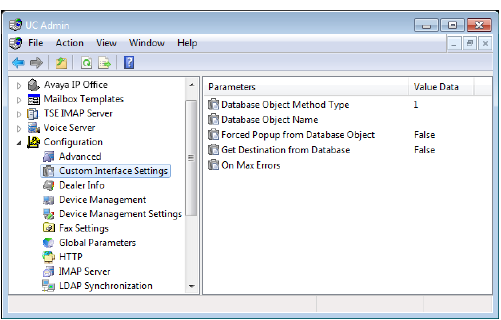
The Custom Interface settings allow you to specify the configurations that deal with integrating a third party database into the UC system.
|
Setting |
Function |
|---|---|
|
Database Object Method Type |
Enter a value of 1 to support PIN-to-mailbox translations only. Enter a value of 2 (recommended) to provide a richer set of Interactive Voice Response (IVR) functionality. |
|
Database Object Name |
Set the value to Object name.Get Destination, where Object name is the calling program name. |
|
Forced Popup from Database Object |
Select True to enable the forcing of pop ups from the database. Select False to disable this parameter. |
|
Get Destination from Database |
Select True to enable the retrieving of the folder destination from the database. Select False to disable this parameter. Pertains to the IVR object. |
|
On Max Errors |
Select Hang Up to instruct the system to disconnect from the third party database in situations where too many errors occur. Select Operator to switch to the operator in situations where too many errors occur. |
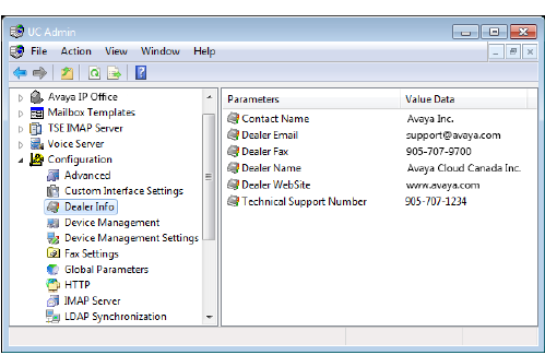
The Dealer Information settings allow you to specify the information of the dealer who has installed the UC system.
|
Setting |
Function |
|
Contact Name |
Shows the dealer representative contact name. |
|
Dealer Email |
Shows the dealer contact email address. |
|
Dealer Fax |
Shows the dealer contact fax number. |
|
Dealer Name |
Shows the dealer company name. |
|
Dealer WebSite |
Shows the dealer company website. |
|
Technical Support Number |
Shows the dealer technical support phone number. |
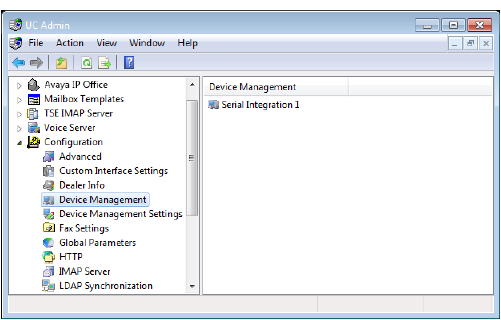
Device Management allows you to add and manage the integration of specific devices with the UC application.
The following devices are managed here. Please refer to the appropriate sections for more information.
•Local Area Paging Device
•Serial Integration Device
•Caller ID Device
•CTI Serial Integration Device
•CTI TCP/IP Integration Device
|
Note: After adding and configuring devices, you can always edit device settings by clicking |
Local Area Paging Device
Local Area Paging is a module that allows you to use the pager function to notify you when you receive a call or message. In the Local Area Device tab, you can specify the associated settings to your paging device.
|
Note: The device settings that are selected must match the hardware settings of your pager in order to function properly. |
TCP/IP Connection
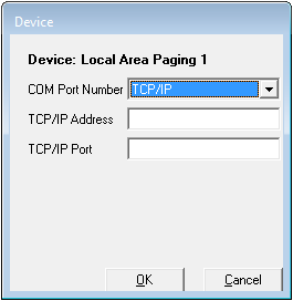
COM Port Number: From the dropdown menu, select the method through which the device will be connected to the UC server. If you are using a COM port instead of TCP/IP, please refer to the COM port section below.
TCP/IP Address: Enter the IP address of the LAP device that the UC server can connect to.
TCP/IP Port: Enter the port number of the LAP device that the UC server can connect to.
COM Port Connection
COM Port Number: From the dropdown menu, select the method through which the device will be connected to the UC server. If you are using TCP/IP as opposed to a COM port please refer to the TCP/IP section above.
|
Note: The value ranges in the COM Port Number/Baud Rate/Parity/Data Bits/Stop Bits/Padding fields are entirely dependent on the switch employed by your system. Consult with your Switch Administrator before altering these values. |
Baud Rate: From the dropdown menu, select the rate (speed) of communication between the UC server and the connected device.
Parity: From the dropdown menu, select the value to be used in determining the integrity of data.
Data Bits: From the dropdown menu, select the number of bits to be used to represent one character of data.
Stop Bits: From the dropdown menu, select which last two bits are to indicate the end of a word.
Padding: From the dropdown menu, select a value to be used to prefix or pad an extension number.
Carrier Detect: Enter a value (in milliseconds) that the modem is to wait before indicating that the first packets of data have been received.
Clear To Send: Enter a value (in milliseconds) that the receiving station is to wait before indicating that it is ready to accept data.
Data Set Ready: Enter a value (in milliseconds) that the modem is to wait before indicating to the PC that it is able to accept data.
Request To Send: Enter a value (in milliseconds) that the node is to wait before attempting to initiate the sending of data.
Validation Time: Enter a value (in seconds) that the system is to wait before checking that data has been successfully sent or received.
Integration With LAP: Enable the checkbox.
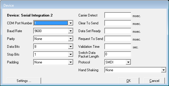
Serial Integration Device
TCP/IP Connection
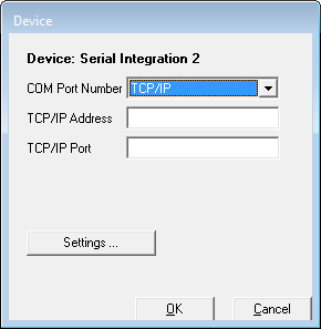
COM Port Number: From the dropdown menu, select the method through which the device will be connected to the UC server. If you are using a COM port as opposed to TCP/IP please refer to the COM port section below.
TCP/IP Address: Enter the IP address of the SMDI device that the UC server can connect to.
TCP/IP Port: Enter the port number of the SMDI device that the UC server can connect to.
COM Port Connection

COM Port Number: From the dropdown menu, select the method through which the device will be connected to the UC server. If you are using TCP/IP as opposed to a COM port please refer to the TCP/IP section above.
|
Note: The value ranges in the COM Port Number/Baud Rate/Parity/Data Bits/Stop Bits/Padding fields are entirely dependent on the switch employed by your system. Consult with your Switch Administrator before altering these values. |
Baud Rate: From the dropdown menu, select the rate (speed) of communication between the UC server and the connected device.
Parity: From the dropdown menu, select the value to be used in determining the integrity of data.
Data Bits: From the dropdown menu, select the number of bits to be used to represent one character of data.
Stop Bits: From the dropdown menu, select which last two bits are to indicate the end of a word.
Padding: From the dropdown menu, select a value to be used to prefix or pad an extension number.
Carrier Detect: Enter a value (in milliseconds) that the modem is to wait before indicating that the first packets of data have been received.
Clear To Send: Enter a value (in milliseconds) that the receiving station is to wait before indicating that it is ready to accept data.
Data Set Ready: Enter a value (in milliseconds) that the modem is to wait before indicating to the PC that it is able to accept data.
Request To Send: Enter a value (in milliseconds) that the node is to wait before attempting to initiate the sending of data.
Validation Time: Enter a value (in seconds) that the system is to wait before checking that data has been successfully sent or received.
Switch Data Packet Length: Enter the maximum digit length of the packets being sent.
Protocol: From the dropdown menu, select the type of serial integration standard to be used (SMDI, MCI or User Defined).
Hand Shaking: From the dropdown menu, select the protocol to be employed in establishing communication between your system and another device.
|
Note: The value in the Hand Shaking field is of considerable importance, and may require several attempts to set properly. |
|
Hint: For the Settings button, refer to the section on Device Management Settings. |
Caller ID Device
The Caller ID Device dialog box indicates the specifications of the Caller ID Device you are using.
TCP/IP Connection
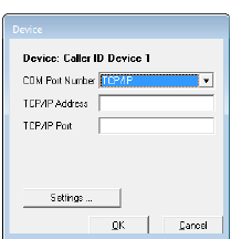
COM Port Number: From the dropdown menu, select the method through which the device will be connected to the UC server. If you are using a COM port as opposed to TCP/IP please refer to the COM port section below.
TCP/IP Address: Enter the IP address of the Caller ID device that the UC server can connect to.
TCP/IP Port: Enter the port number of the Caller ID device that the UC server can connect to.
COM Port Connection
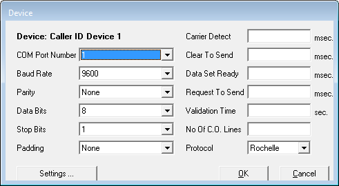
COM Port Number: From the dropdown menu, select the method through which the device will be connected to the UC server. If you are using TCP/IP as opposed to a COM port please refer to the TCP/IP section above.
|
Note: The value ranges in the COM Port Number/Baud Rate/Parity/Data Bits/Stop Bits/Padding fields are entirely dependent on the switch employed by your system. Consult with your Switch Administrator before altering these values. |
Baud Rate: From the dropdown menu, select the rate (speed) of communication between the UC server and the connected device.
Parity: From the dropdown menu, select the value to be used in determining the integrity of data.
Data Bits: From the dropdown menu, select the number of bits to be used to represent one character of data.
Stop Bits: From the dropdown menu, select which last two bits are to indicate the end of a word.
Padding: From the dropdown menu, select a value to be used to prefix or pad an extension number.
Carrier Detect: Enter a value (in milliseconds) that the modem is to wait before indicating that the first packets of data have been received.
Clear To Send: Enter a value (in milliseconds) that the receiving station is to wait before indicating that it is ready to accept data.
Data Set Ready: Enter a value (in milliseconds) that the modem is to wait before indicating to the PC that it is able to accept data.
Request To Send: Enter a value (in milliseconds) that the node is to wait before attempting to initiate the sending of data.
Validation Time: Enter a value (in seconds) that the system is to wait before checking that data has been successfully sent or received.
No. Of CO Lines: Enter the number of CO lines that are utilized by the current setup.
Protocol: From the dropdown menu, select the type of serial integration standard to be used (SMDI, MCI or User Defined).
|
Hint: For the Settings button, refer to the section on Device Management Settings. |
CTI Serial Integration Device
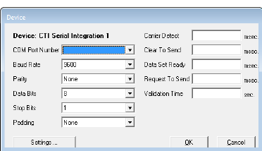
The CTI Serial Integration allows you to define the type of CTI integration for CSTA integration that you are receiving through a serial link.
COM Port Number: From the dropdown menu, select the method through which the device will be connected to the UC server. If you are using TCP/IP as opposed to a COM port please refer to the TCP/IP section above.
|
Note: The value ranges in the COM Port Number/Baud Rate/Parity/Data Bits/Stop Bits/Padding fields are entirely dependent on the switch employed by your system. Consult with your Switch Administrator before altering these values. |
Baud Rate: From the dropdown menu, select the rate (speed) of communication between the UC server and the connected device.
Parity: From the dropdown menu, select the value to be used in determining the integrity of data.
Data Bits: From the dropdown menu, select the number of bits to be used to represent one character of data.
Stop Bits: From the dropdown menu, select which last two bits are to indicate the end of a word.
Padding: From the dropdown menu, select a value to be used to prefix or pad an extension number.
Carrier Detect: Enter a value (in milliseconds) that the modem is to wait before indicating that the first packets of data have been received.
Clear To Send: Enter a value (in milliseconds) that the receiving station is to wait before indicating that it is ready to accept data.
Data Set Ready: Enter a value (in milliseconds) that the modem is to wait before indicating to the PC that it is able to accept data.
Request To Send: Enter a value (in milliseconds) that the node is to wait before attempting to initiate the sending of data.
Validation Time: Enter a value (in seconds) that the system is to wait before checking that data has been successfully sent or received.
|
Hint: For the Settings button, refer to the section on Device Management Settings. |
CTI TCP/IP Integration Device
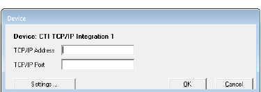
The TCP/IP Integration allows you to specify CTILINK or CSTA integration over TCP/IP.
TCP/IP Address: Enter the IP address of the device that the UC server can connect to.
TCP/IP Port: Enter the port number of the device that the UC server can connect to.
|
Hint: For the Settings button, refer to the section on Device Management Settings. |
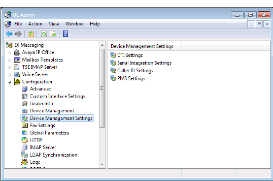
Device Management Settings allow you to configure the specifics of the devices that are integrated with the UC application. Although you are prompted to specify device settings when adding new devices, you can conveniently edit these settings through this feature.
|
Note: These settings may play an integral part in the proper integration of your PBX and other devices to the UC server. The settings will often take affect even in the absence of separate hardware since the PBX itself must be configured (e.g. CTI Settings should be completed for proper CTI functionality integration). |
Device Management Settings consists of the following items. Please refer to the individual sections for more information.
•CTI Settings
•Serial Integration Settings (SMDI)
•Caller ID Settings
CTI Settings
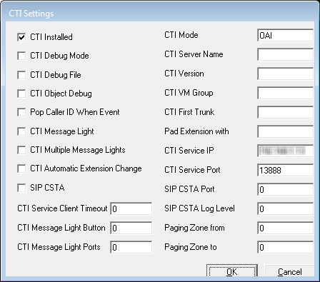
CTI Installed: Enable this checkbox to indicate that a CTI link from the PBX is active and available for monitoring.
CTI Debug Mode: Enable this checkbox to monitor and log the CTI events.
CTI Debug File: Enable this checkbox to enable the creation of a debug file from CTI event monitoring.
CTI Object Debug: Enable this checkbox to enable object debug.
Pop Caller ID When Event: Enable this checkbox to activate screen pop-ups on station-to-station and internal dialing.
CTI Message Light: Enable this checkbox to use the CTI serial link to light a message light.
CTI Multiple Message Lights: Enable this checkbox to use the CTI serial link to light multiple message lights.
CTI Automatic Extension Change: Enable this checkbox to use the CTI serial link to enable automatic extension changes when altering the default address of a Mailbox.
SIP CSTA: This item is no longer supported.
CTI Service Client Timeout: Enter the length of time that the system will continue to retry connections before failing.
CTI Message Light Button: Enter the numeric digit on the phone keypad that will enable the message light option. This is an optional setting for activating lights through the link.
CTI Message Light Ports: Enter the ports on the switch where the lights are located.
CTI Mode: Enter the type of CTI events that the system is to look for.
CTI Server Name: Enter the server machine or phone system on the network that will be sending the CTI events.
CTI Version: Enter the version description of the CSTA or CTI link on the switch.
CTI VM Group: Enter the VM ports that are to be monitored for events.
CTI First Trunk: Enter the first VM port to monitor.
Pad Extension with: Enter a numerical digit to represent the number of spaces that will pad those unused in the screen popup when an incoming call contains a string of digits less than the maximum specified.
CTI Service IP: Enter the IP address used by the CTI Service.
CTI Service Port: Enter the port used by for CTI Service traffic.
SIP CSTA Port: This item is no longer supported.
SIP CSTA Log Level: This item is no longer supported.
Paging Zone from: Enter the appropriate PBX number.
Paging Zone to: Enter the appropriate PBX number.
Serial Integration Settings
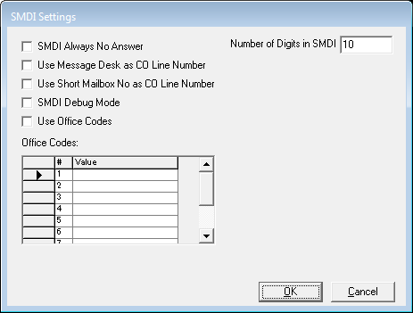
SMDI Always No Answer: Enable this checkbox to treat all busy / no answer conditions as no answer.
Use Message Desk as CO Line Number: Enable this checkbox for multi-tenanting configuration - message desk configuration must be programmed on the phone system.
Use Short Mailbox No as CO Line Number: Enable this checkbox for multi-tenanting purposes.
|
Note: This option must be programmed on the phone system. |
SMDI Debug Mode: Enable this checkbox to log all SMDI events.
Use Office Codes: Enable this checkbox for central office integration in a centralized voice mail setup.
Number of Digits in SMDI: Enter the maximum number of digits in an SMDI string for the calling and called parties. The standard setting is 7 or 10 digits in length.
Office Codes - Value fields: Enter the codes used to distinguish one office from another. These will be the first three digits which comprise that part of a phone number following the area code.
Copy SMDI Packet to Remote Servers: In a High Availability environment, enabling this option will send SMDI packet data to the other servers in the array.
Caller ID Settings
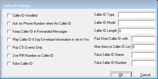
Caller ID Installed: Enable this checkbox to use third-party a device for passing the Caller ID.
Ask for Phone Number when No Caller ID: Enable this checkbox to prompt the caller for a phone number when device fails to detect one.
Keep Caller ID in Forwarded Messages: Enable this checkbox to maintain and attach original Caller ID information to the message during forwarding.
Play Caller ID if Say Date and Time is set to Yes: Enable this checkbox to play time and date stamp in addition to Caller ID information.
Pop CTI Events Only: Enable this checkbox to perform screen pop-ups only on events driven by the CTI Link.
Use PIN Number as Caller ID: Enable this checkbox to treat PIN number inputs as Caller ID information.
Fake Caller ID: Enable this checkbox to define a fake number to use on all calls.
Caller ID Type: Enter the type of device connected for tracking caller ID such as Rochelle, Zeus or CTI.
Caller ID Mode: Enter the mode in which the system receives the caller ID information, such as inband, SMDI, or CTILink.
Caller ID Length: Enter the maximum digits that can be sent for caller ID packets.
Pad Short Caller ID: Enter any prefixes (such as an area code) when only 7 digits are sent. It will pad the number to ensure a proper lookup in a database.
Max Items in Caller ID List: Enter the maximum list view for the system administration.
Fake Caller ID Name: Enter a name that you want to appear on the screen pop-ups.
Fake Caller ID Number: Enter the number you want to appear on the caller ID screen pop-ups and messages.
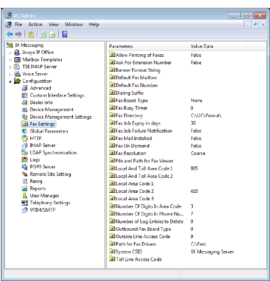
Fax Settings allow you to specify the information required for a user to be able to receive a fax into the Auto Attendant. Fax On Demand can be used to forward the fax to an appropriate Mailbox or location.
|
Setting |
Function |
|---|---|
|
Allow Printing of Faxes |
This indicates whether or not users can print received faxes via the telephone. Select True or False. |
|
Ask For |
This indicates whether or not to ask the caller for an extension number to put on the received faxes when using the Fax Mail module. Select True or False. |
|
Default Fax Mailbox |
This defines the mailbox that incoming faxes will be delivered to if no destination is given. Select a company, then a specific company mailbox. |
|
Banner Format String |
A string value denoting how the fax banner will appear. |
|
Default Fax Number |
This defines the default number to dial to print received faxes. Enter a number. |
|
Dialing Suffix |
This is the long distance account code required in order to make toll calls from the Phone system. This will apply if the default fax number is an external toll call. |
|
Fax Board Type |
This identifies the fax board that is integrated with the system. Select one of the fax boards. Applies to inbound faxes only. |
|
Fax Busy Timer |
This indicates the number of seconds to wait after initiating a transfer to the fax port before reverting back to an idle state. |
|
Fax Directory |
This specifies the path for the directory that contains the fax documents. |
|
Fax Job Expiry in days |
Specify the number of days to keep fax job status records. |
|
Fax Job Failure Notification |
Choose whether or not to send a notification email to the sender when a fax attempt fails. The default is False (do not send notification). |
|
Fax Mail Installed |
This indicates whether or not the Fax Mail option is enabled for receiving faxes. Select True or False. |
|
Fax On Demand |
This indicates if the Fax On Demand option is enabled. Select True or False. |
|
Fax Resolution |
This sets the resolution type for fax transmissions. |
|
File and Path |
This is the path to the directory containing the fax viewer application. |
|
Local And Toll |
This is the area code(s) in your region that covers both local and toll calls. |
|
Local And Toll |
This is the area code(s) in your region that covers local calls. NOTE: Code Number 1 for both entries is for 7-digit dialing. Code Number 2 and higher are for 10-digit dialing. |
|
Local Area Code 1 |
This is the first local area code for the country. |
|
Local Area Code 2 |
This is the second local area code for the country. |
|
Local Area Code 3 |
This is the third local area code for the country. |
|
Number Of Digits |
This indicates how many digits to view from the entered number as the Area Code. |
|
Number Of Digits |
This indicates how many digits to view from the entered number as the Phone Number. |
|
Number of Log Entries |
This sets the housekeeping rules for deleting old fax log entries starting from the oldest record. |
|
Outbound Fax Board Type |
This indicates the type of fax board for outgoing faxes. |
|
Outside Line Access Code |
This sets the code for line access to dial out a fax-on-demand call. |
|
Path for Fax Drivers |
This indicates the path to the directory that stores the fax drivers. |
|
System CSID |
This specifies the fax header information. |
|
Toll Line Access Code |
This defines the code for Alternate Carrier Access. |
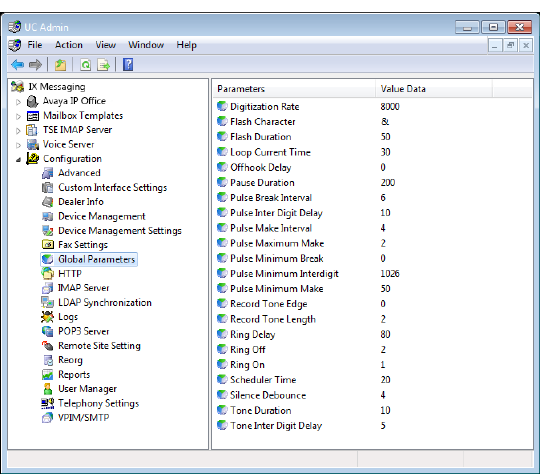
Global Parameters allow for the configuration of specific boards and pulse detection.
|
Setting |
Function |
|---|---|
|
Digitization Rate |
This is the value used for digitization. |
|
Flash Character |
This is the character used in a dial string to indicate that a hook flash has occurred. |
|
Flash Duration |
This is the value of the duration of the hook flash in 10msec intervals. |
|
Loop Current Time |
The value of the minimum time that the loop current must be off before Loop Current CST can be generated (10msec intervals). |
|
Offhook Delay |
The value for the offhook delay time (10msec intervals). |
|
Pause Duration |
The value of the length of a pause used in a dialing string. (10msec intervals). |
|
Pulse Break Interval |
The value of the break interval for pulse dialing (10msec increments). |
|
Pulse Inter Digit Delay |
The value of the inter digit interval for pulse dialing (10msec increments). |
|
Pulse Make Interval |
The value of the make interval for pulse dialing (10msec increments). |
|
Pulse Maximum Make |
The value of the maximum make pulse time for pulse dialing (10msec increments). |
|
Pulse Minimum Break |
The value of the minimum break interval for valid loop pulse dialing (10msec increments). |
|
Pulse Minimum Interdigit |
The value of the minimum inter digit interval for pulse dialing (10msec increments). |
|
Pulse Minimum Make |
The value of the minimum make interval for pulse dialing (10msec increments). |
|
Record Tone Edge |
The value for the Record DTMF filter time (10msec increments). |
|
Record Tone Length |
Indicates the event edge to use for record tone: 1=event detection on trailing edge of tone 2=event detection on leading edge of tone |
|
Ring Delay |
The value of the wait delay after which the ring count is reset ( 100msec increments). |
|
Ring Off |
The value of the minimum Ring Off interval to detect an incoming ring (100msec increments). |
|
Ring On |
The value of the minimum Ring On interval to detect an incoming ring (100msec increments). |
|
Scheduler Time |
The value of the Scheduler Time Slice, expressed as the maximum number of timer ticks (expressed in 1/20 sec), before the driver must return control to the program (50msec increments). |
|
Silence Debounce |
The value of the Silence message debounce interval (10msec increments). |
|
Tone Duration |
The value of the duration of dialed DTMF tones (10msec increments). |
|
Tone Inter Digit Delay |
The value of the inter digit tone dialing delay (10msec increments). |
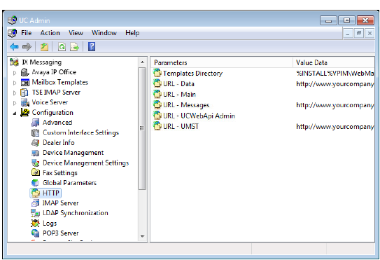
HTTP Settings allows you to configure settings to view members of your voice mail system, and the status of each Mailbox through any Internet connection.
|
Caution: These settings are managed through the Web Mail Utility and should not be changed from here. For details, refer to Messaging Configuration on page 652 in this manual. |
|
Setting |
Function |
|---|---|
|
Templates Directory |
Specify the path to the location on the hard drive where templates are stored. By default, this is the UC Installation directory on the local drive. |
|
URL - Data |
Displays the Internet accessible address of the UC Server where the necessary icons and image files are stored. |
|
URL - Main |
Enter the Internet accessible address for the UC Server. Client applications (e.g. Web Access) use this address for their traffic. |
|
URL - Messages |
This is the path to the Internet accessible voice and fax message store. |
|
URL - UCWebApiAdmin |
(Optional) For sites that want to physically separate Admin and End-User functions, enter the Internet accessible address you want to use for all Admin client traffic (e.g. Web Admin). End-user content will continue to use the URL - Main address. * |
|
URL - UMST |
Contains the path to the Internet accessible files needed for web based telephone control. |
* - Typically, this solution requires a second NIC to be installed in the voice server. All admin traffic passes through one card, while end-user traffic uses the other providing a physical separation of the flow of data. This prevents end-user accounts from being able to monitor or corrupt administrator traffic.
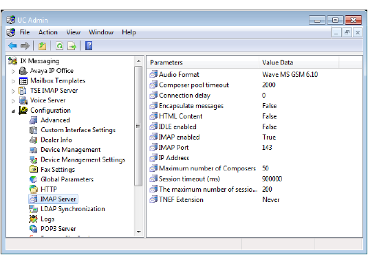
IMAP Server settings allow you to configure IMAP messaging behavior.
|
Setting |
Function |
|
Audio Format |
This is the audio format for messages sent through IMAP. |
|
Composer pool timeout |
The maximum length of time in milliseconds one must wait before a new composer is created (for message creation). Note: Composer is the IMAP component that translates messages to mime format. |
|
Connection delay |
This is the allowable length of time to wait to connect. |
|
Encapsulate messages |
Select True to allow the encapsulation of messages, False to disable the option. |
|
HTML Content |
Set to True to allowing the sending of messages in HTML format. |
|
IDLE Enabled |
Set to True to enable Idle mode. |
|
IMAP Enabled |
Set to True to enable IMAP. |
|
IMAP Port |
This is the IMAP port. |
|
IP Address |
This is the default IMAP gateway address. |
|
Maximum number of Composers |
The composer is the means by which information from the DB is converted to the MIME format. A ratio of 1 composer to 3 users in suggested. For a system of 300 users, enter a value of 100. |
|
Session timeout (ms) |
This is the length of time (in milliseconds) to wait before timing out the session. |
|
The maximum number of sessions |
This is the maximum allowable number of IMAP sessions. |
|
TNEF Extension |
This is the message class or ID. |
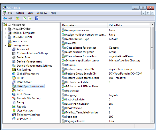
LDAP Synchronization settings allows the administrator to specify the network accessible directory information for the Internet Protocol (IP).
Email clients and other programs and services use this information to reach needed files.
|
Settings |
Function |
|---|---|
|
Anonymous access |
Select True if an anonymous bind (connection) is to be used. This allows login by any client, without authentication. |
|
Assign mailbox number or company name if not user defined |
Set this to True to have the system route any undefined imports to the first available user of the first defined company. When set to False, undefined LDAP imports will fail. |
|
Authorization Type |
Allows you to select the synchronization authorization type. Select Simple if simple authentication is to be used, or GSS if GSS authentication is to be used. |
|
Base DN |
This is for the unique base name. |
|
Class schema for contact |
This is for the object’s class name to be synchronized with Public Contact. |
|
Class schema for group |
This is for the object’s class name to be synchronized with Feature Group. |
|
Class schema for mailbox |
This is for the object’s class name to be synchronized with mailbox. |
|
Directory application server |
Allows you to select the LDAP directory server. Your choices are Microsoft Active Directory, Novell eDirectory, iPlanet, or Others. |
|
Domain |
This is for the User’s domain name. |
|
Feature Group Filter DN |
This is a data string describing what you are looking for on the directory server. |
|
Feature Group Search DN |
This is a data string describing the directory server location. This is the feature group search location. |
|
Feature Group search scope |
Select One level for a one-level search, or Sub-tree level for a multiple-level search. |
|
FG Last check date |
This value is read-only. |
|
FG Last check USN or Date |
This value is read-only. |
|
Host name |
This is for the directory server name. |
|
Language |
Allows you to select the language of the active system. |
|
Last check date |
This value is read-only. |
|
LDAP Port number |
Specify the LDAP port number. |
|
LDAP Version |
Specify the LDAP protocol version. |
|
Mailbox Template Number |
Apply the selected template number to imported accounts. The number is found in the Mailbox Template section of UC Admin. |
|
Page size |
Indicates the number of entries to show per page when retrieving results from the server |
|
Paging allowed |
Select True to enable paging specifications. |
|
Password |
This is for the administrator password. |
|
PC Last check date |
This value is read-only. |
|
PC Last check USN or Date |
This value is read-only. |
|
Pop up the query window |
Set to True to enable query window popup, set to False to disable. |
|
Public contact Filter DN |
This is a data string describing what you are looking for on the directory server |
|
Public contact Search DN |
This is a data string describing the directory server location. This is the public contact search location. |
|
Public contact search scope |
Select One level for a one-level search, or Sub-tree level for a multiple-level search |
|
SSL connection |
Select True if Secure Socket Layers are being used |
|
Synchronization direction |
Usually this will be Only Directory to Database. For synchronization with an IMAP source, selecting Both ways will synch updated information only. |
|
Synchronization Time (the last time) |
This value is read-only |
|
Synchronization timeout |
Allows you to specify the maximum number of seconds before a connection and/or operation times out |
|
Synchronization Type |
Allows you to select the type of synchronization to occur. Select DateTime only when you want synchronization between the messaging and directory servers to occur on a time basis. In most cases, you will select USN. |
|
Synchronization USN (The last value) |
This value is read-only. |
|
Synchronize deletions |
This item is no longer supported. |
|
Synchronize nested |
For companies that have a hierarchical organization (ie. Sales on top, with regions below), setting this option to True will force LDAP to maintain the structure. Set to False to flatten the structure into the highest layer (i.e. all contacts into Sales). |
|
Timeout |
Allows you to specify the maximum number of seconds before a connection and/or operation times out. |
|
Tombstone object DN |
This item is no longer supported. |
|
Update phone number |
Select True to allow a phone number(s) to be updated, or False to deny that option. |
|
User DN |
This is the unique name for the User (admin). |
|
User Filter DN |
This is a data string describing what you are looking for on the directory server. |
|
User Search DN |
This is a data string describing the directory server location. This is the user search location. |
|
User search scope |
Select One level for a one-level search, or Sub-tree level for a multiple-level search |
|
UUID |
Specify the LDAP attribute to use as a Universally Unique Identifier in case the usual ID (i.e FirstName+LastName) may change. |
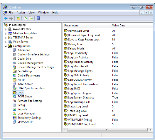
Logs settings allow you to specify report logging on all system components.
|
Note: Log and Debug information allow technical support representatives to more accurately pinpoint server issues. If there are no problems, however, you should, in order to save resources, leave your Log and Debug settings as default or even disable them entirely. |
|
Settings |
Function |
|---|---|
|
Admin Log Level |
This will create a log file for all Admin activity. |
|
Business Object Log Level |
This will create a log file for all EE Application Manager activity. |
|
Days to Keep Report Logs |
Defines the number of days that data is stored in log files. These are the logs that contain the data used for generating Web Reports, not system performance/maintenance monitoring data. |
|
Debug Level |
This sets the level of information sent to a log file when Debug mode is activated. Enter a number between 0 (least) and 5 (most), depending on the level of detail required. |
|
Debug Mode |
Debug mode for all main voice server activities. |
|
Log Fax Activity |
Logs all fax activity. |
|
Log Lan Activity |
This will create a log file for all Lan activity. |
|
Log Mailbox Activity |
This will create a log file for all Mailbox activity. |
|
Log Mass Recall |
Logs all Mass Recall activity. |
|
Log Message Lights |
Logs all Message Light activity. |
|
Log Queue Activity |
Creates a log file for all Queue activity. |
|
Log Record Termination |
Creates a log file for all Record termination activity |
|
Log SMDI |
Logs all SMDI activity. |
|
Log Speech Engine |
Creates a log file for all Log Speech Engine activity. |
|
Log System Statistics |
Creates a log file for all system statistics. |
|
Log Wakeup Calls |
Creates a log file for all Wakeup Call activity. |
|
Status Log Level |
Select a value that indicates the level at which status logs should be created. Set to 0 = Least detailed. Set to 5 = Most detailed. |
|
Trace Log Level |
Select a value that indicates the level at which trace logs should be created. Set to 0 = Least detailed. Set to 5 = Most detailed. |
|
UMST Log Level |
This will create a log file for all UMST activity. |
|
VPIM/SMTP Debug |
This allows for VPIM/SMTP debug. |
|
VPIM/SMTP Log Level |
This indicates the level of information sent to a log file for all VPIM/SMTP activity, provided debug is activated. |
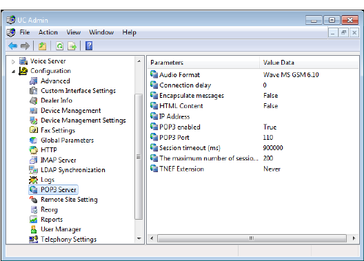
IMAP4 and POP3 are no longer supported.
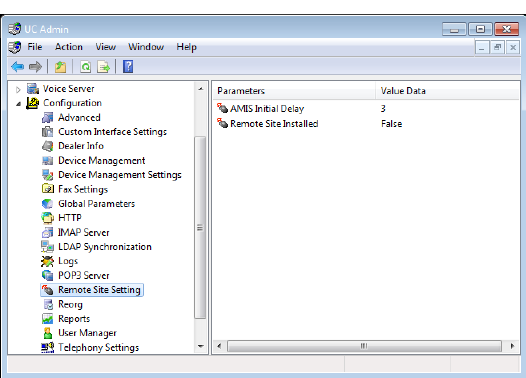
Remote Site settings allow you to configure both AMIS and VPIM parameters.
|
Setting |
Function |
|
AMIS Initial delay |
The value of the delay, in seconds, that the system will use to ignore the C tone sent by AMIS. This is required only if there is a C tone sent via Inband signaling from the PBX. Set to zero if no delay is needed. |
|
Remote Site Installed |
Indicates if remote networking is installed. Set equal to True for AMIS/VPIM.* |
* -- This setting must be configured as True on all servers in an HA environment since it is not automatically synchronized between them.
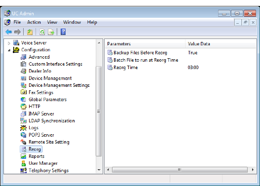
Reorg settings allow you to specify the rules to activate and run the function that cleans and compacts the database.
|
Setting |
Function |
|
Backup Files Before Reorg |
Indicates whether or not to back up the database files before initiating the reorg. |
|
Batch Files to run at Reorg Time |
Defines a batch file to initiate before the reorg is performed. (i.e. network or tape drive backup) |
|
Reorg Time |
Sets the time of day (24-hour format) to initiate the reorg function. Select the Disable Reorg checkbox to disable the reorg function. |
|
Note: Depending on the size of the system (e.g. number of users), the time it takes Reorg to complete its tasks will vary. All services are stopped during this time. |
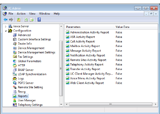
Reports settings allow you to enable or disable specific component activity reports.
|
Setting |
Function |
|
Administration Activity Report |
Select True to allow for the creation of administration activity reports. |
|
ASR Activity Report |
Select True to allow for the creation of ASR activity reports. |
|
Call Activity Report |
Select True to allow for the creation of call activity reports. |
|
Mailbox Activity Report |
Select True to allow for the creation of mailbox activity reports. |
|
Message Activity Report |
Select True to allow for the creation of message activity reports. |
|
Notification Activity Report |
Select True to allow for the creation of notification activity reports. |
|
Remote Sites Activity Report |
Select True to allow for the creation of remote sites activity reports. |
|
Telephony Activity Report |
Select True to allow for the creation of telephony activity reports. |
|
Transfer Activity Report |
Select True to allow for the creation of transfer activity reports. |
|
iLink Pro Desktop Activity Report |
Select True to allow for the creation of Client Manager activity reports. |
|
Voice Menu Activity Report |
Select True to allow for the creation of voice menu activity reports. |
|
Web Access Activity Report |
Select True to allow for the creation of Web Access activity reports. |
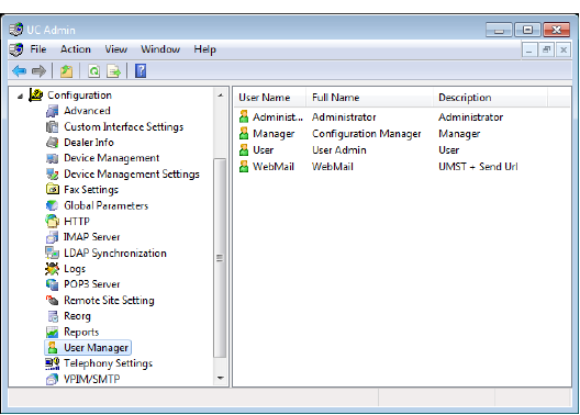
The User Manager configuration setting allows you to specify one or more Administrators and the system properties that they control. The Administrators can have limited control over the UC systems (i.e. Edit PBX), up to Full Access.
Edit / Add User
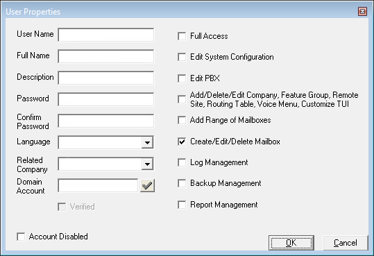
Specify the following:
User Name: Enter the name of the administrator.
Full Name: Enter the administrator’s full name.
Description: Enter the title or purpose of this administrator.
Password: Create the administrator’s password.
Confirm Password: Re-enter the password.
Language: Select the language preference for this administrator.
|
Note: If multiple language support is needed for your administrators, a new administrator must be created for each language. When accessing the Supervisor Menu in the TUI, the password entered for the configured Administrator account will define the language to play. |
Related Company: Select the companies this administrator has administrative rights over.
Account Disabled: Select to disable this account.
Domain Account: Use this field to allow administrators to login to the admin console using another domain’s credentials. Enter a name and domain (e.g. [email protected] for Google and Office 365 credentials, domain\username for Windows). Click the check ![]() to verify access to the domain server.
to verify access to the domain server.
When logging in to the console, choose the appropriate provider, then enter your credentials at the prompt.
|
Warning: Configuring domain login on any Messaging Admin account will activate it for ALL accounts. If different credentials are required for each account, each must be configured separately. |
Enable the following tasks by selecting the corresponding checkbox:
|
Task |
Function |
|
Full Access |
Allows a user full access to the system. |
|
Edit System Configuration |
Allows the administrator to edit system configuration files. |
|
Edit PBX |
Allows the administrator to edit the PBX. |
|
Add/Delete/Edit Company, Feature Group, Remote Site, Routing Table, Voice Menu, Customize TUI |
Allows the administrator to add, edit, and delete a company, feature group, remote site, routing table, voice menu, and to customize a TUI. |
|
Add Range of Mailboxes |
Allows the administrator to add a range of mailboxes. |
|
Create/Edit/Delete Mailbox |
Allows the administrator to create, edit, and delete a mailbox. |
|
Log Management |
Allows the administrator to set and define logs. |
|
Backup Management |
Allows the administrator to perform and define backup management. |
|
Report Management |
Allows the administrator to define and create reports and run the Web Reporter utility. |
|
Note: You must be logged into the server as an administrator to be able to edit and delete User Manager settings. |
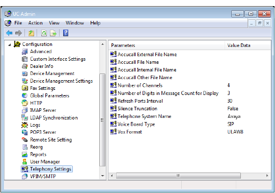
Use Telephony Settings to configure the behavior of the telephone phone system.
|
Setting |
Function |
|---|---|
|
Accucall External File Name (Brooktrout only) |
Indicates the external filename used. |
|
Accucall File Name (Brooktrout only) |
Indicates the accucall filename used. |
|
Accucall Internal File Name (Brooktrout only) |
Indicates the internal filename used. |
|
Accucall Other File Name (Brooktrout only) |
Indicates the other filename used. |
|
Norstar 7310 Dialing*** |
Allows for out-dialing to be performed on the virtual set dial pad rather than via the voice boards (Dialogic). |
|
Norstar Busy Time Out*** |
Used to set timer for Busy Transfer. |
|
Number of Channels |
Indicates the total number of voice channels installed. *Must be set by the administrator. |
|
Number of Digits in Message Count for Display |
This value sets the number of digits used to send to a display pager or a supported display PBX telephone indicating the number of the message sending the notification. |
|
Pulse Detection Enabled |
Indicates whether or not to use pulse detection. Requires the correct hardware. |
|
Refresh Ports Interval |
Indicates the time interval between generating an offhook/onhook sequence on each port. Used to keep ports listed as active in certain PBXs. |
|
Silence Truncation |
Removes silence from recording (used for Rhetorex only). |
|
Telephone System Name |
Indicates the make of the telephone system. |
|
Voice Board Type |
Indicates the type of voiceboard used. |
|
Vox Format |
Indicates the format of all recordings in the system (for example, WAV). |
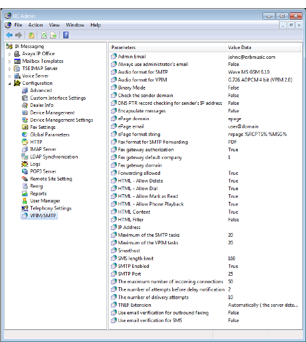
VPIM/SMTP settings allow you to configure VPIM server behavior.
|
Setting |
Function |
|
Admin Email |
Indicates the administrator’s email address. |
|
Always use administrator’s email |
Replaces the sender’s email with that of the admin account. The display will still show the original sender. This is used when receiving messages from outside sources (i.e. Gmail) that may lack vital routing information. |
|
Audio format for SMTP |
This is the audio format for SMTP voice messages. |
|
Audio format for VPIM |
This is the audio format for VPIM voice messages. |
|
Binary Mode |
Set to False to allow binary encoded messages. |
|
Check the sender domain
|
Enable to have the system check the domain of message senders, for purposes of confirming the legitimacy of message source. |
|
DNS PTR record checking for sender’s IP address |
Select True to enable DNS PTR record checking for a sender’s IP address. |
|
Encapsulate messages |
Select True to enable message encapsulation, False to disable. |
|
ePage domain |
Not generally implemented. Used in a proprietary installation. |
|
ePage email |
Not generally implemented. Used in a proprietary installation. |
|
ePage format string |
Not generally implemented. Used in a proprietary installation. |
|
Fax format for SMTP forwarding |
Select either PDF or TIFF for fax handling. Typically used for IMAP systems. The Message Options in each user’s mailbox will override this setting. |
|
Fax gateway authorization |
Enable to authenticate fax gateway before sending a fax message. |
|
Fax gateway default company |
Indicates the default company number for sending of faxes. |
|
Fax gateway domain |
Indicates the domain of the fax gateway. |
|
Forwarding allowed |
Set to True to enable the forwarding of messages from remote machines. |
|
HTML - Allow Delete |
With Send URL, this enables or disables Deletion. |
|
HTML - Allow Dial |
With Send URL, this enables or disables Dialing. |
|
HTML - Allow Mark as Read |
With Send URL, this enables or disables marking a message as Read. |
|
HTML - Allow Phone Playback |
With Send URL, this enables or disables message playback. |
|
HTML Content |
Set to True to allowing the sending of messages in HTML format. |
|
HTML Filter |
Allows for the filtering of HTML in messages to text. |
|
IP Address |
This is the default IP address for SMTP messages. |
|
Maximum of the SMTP tasks |
Indicates how many SMTP messages can be processed at one time. |
|
Maximum of the VPIM tasks |
Indicates how many VPIM messages can be processed at one time. |
|
Notification Email |
Administrator alerts will be sent to the email address entered here. |
|
Smarthost |
In case of a "non-connected" PC, all messages will be sent after being forwarded to this connected host. |
|
SMS Length limit |
Determines the length of a SMS text message. |
|
SMTP Enabled |
Indicates whether or not SMTP is enabled. |
|
SMTP Port |
Indicates the port used for SMTP messaging. |
|
The maximum number of incoming connections |
This is for the maximum number of VPIM/SMTP connections allowed. |
|
The number of attempts before delay notification |
Indicates the number of times a message send attempt will occur before the sender is sent a “message delayed” notification. |
|
The number of delivery attempts |
Indicates the number of times a message delivery attempt will occur before the sender is sent a “message delivery failure” notification. |
|
TNEF Extension |
This is the message class or ID |
|
Use email verification for outbound faxing |
Enable this option to require outbound faxes originating outside the company to be verified through email before sending. An off-site sender, after requesting to send a fax, will receive an email with a link which must be clicked before the fax will be sent. |
|
Use email verification for SMS |
Enable this option to require outbound SMS messages originating outside the company to be verified through email before sending. An off-site sender, after requesting to send an SMS message, will receive an email with a link which must be clicked before the message will be sent. |